Article
KLM busway installation: sequence, joint torque and IP68 potting
How KLM-S busway is installed per the manufacturer's manual: supports every 1.5 m, joint assembly, 80 N·m torque, IP68 potting, tests and hidden-work sign-off.
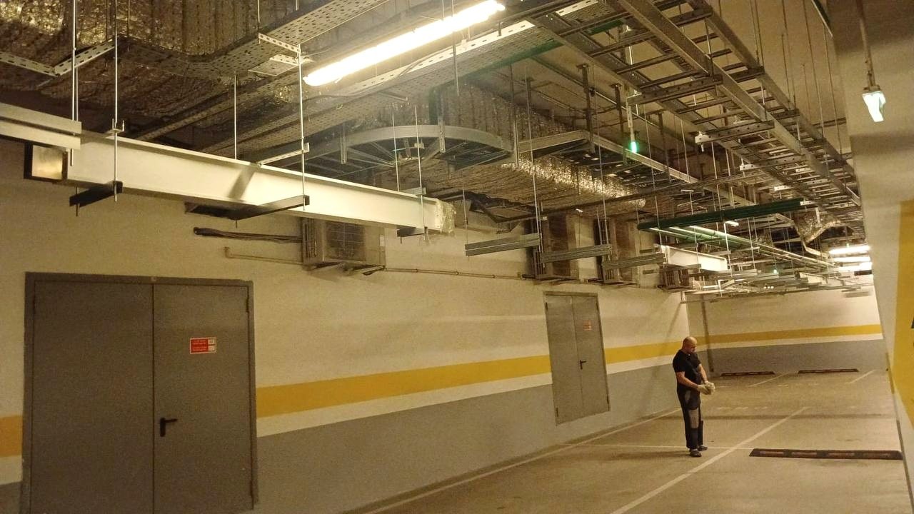
KLM-S trunking busway goes where a single route has to carry thousands of amperes: from uninterruptible power supplies to the main switchboard, through floors and technical rooms. The most important part of such a line is not the aluminium housing but the joints between the sections. How a joint is assembled and tightened decides whether the line runs for years without overheating. Below is the installation sequence as the manufacturer, ALBIMAX METAL LLC, describes it in its manual, plus what the practice of a live building adds to it: we are installing KLM-S lines rated 2000 and 2500 A at Kutuzovsky Prospekt, 32 in Moscow.
This text does not replace the manufacturer's manual or the design: every route has an assembly drawing, and it comes first.
What KLM-S busway is
KLM busway consists of sections up to 3 metres long with aluminium or copper busbars inside an aluminium housing. The length tolerance of a section is ±2 mm. Sections are connected with joint units, and the set of sections, bends, feed units and tap-off boxes is defined by the assembly drawing for the particular project.
The range has two main types: KLM-S, a trunking busway for high currents, and KLM-R, a distribution busway. The trunking busway comes with IP55 and IP68 protection. IP68 is busway in cast insulation: its joints are filled with compound after assembly, so it is not afraid of dust or moisture.
Where installation starts
Before the first section goes up on site, a few things have to be settled:
- Manufacturer's briefing. Before installation a representative of the factory runs a briefing and hands over the documentation. The responsible staff sign an acknowledgement sheet for the manual. Without the signature the manufacturer may refuse warranty service.
- Staff qualification. Installers are examined on the rules for the safe operation of electrical installations and for work at height, and hold an electrical safety group. On our site the route runs at a height of 2.5 to 3.8 metres, so work at height is no formality.
- Receiving. Delivery papers are checked against what has arrived, and the elements are inspected for damage. If something is wrong, a report is drawn up together with the carrier. Claims for missing items and wrong deliveries are accepted within two weeks of receipt.
- Storage. Packaging is removed shortly before installation, and the sections are stored on a flat base in a dry place. Elements with exposed busbars that have been exposed to water, for example after rain or a leak, must not be installed: they go back to the factory.
- Marking out and the neutral conductor. The route is marked out from the working documentation. The position of the neutral conductor is checked separately: where the busway enters a panel parallel to its door, the neutral must be the one nearest the door; where it enters perpendicular to the door, on the right.
Supports: a 1.5 metre pitch and 3 millimetres of tolerance
Supports go in first, before the sections are lifted. According to the manufacturer's manual they are placed at no more than 1.5 metres, and after fixing the busway must not deviate from its axis by more than 3 mm in any plane.
A support is mandatory under bends, end feed units, the flexible part of a flexible module and a reduction module. A support must not obstruct the installation of tap-off boxes or cover the joint covers. Fixings are selected so that the joint units themselves carry no mechanical load.
There is also a limit that the designer builds in beforehand: straight runs need CML expansion sections that take up thermal expansion. For IP55 with aluminium busbars the interval is no more than 30 metres, with copper 45, and for cast IP68 40 metres.
Lifting and laying the sections
A 3-metre section on our lines weighs up to 100 kg. It is not lifted to height by hand: this takes hoists, winches or mobile scaffold towers, sound slings with load rating tags and several people. The manual expressly forbids lifting a section by the ends of the busbars, dragging it over the floor, climbing on the busway and using it as a platform or as a support for other services.
Adjacent sections are laid symmetrically with a gap of 22 mm ±2 mm. Small manufacturing deviations are absorbed by spreading the gaps evenly over the joints along the whole route.
Assembling a joint: where reliability comes from
This is where mistakes are made most often. The order is as follows:
- Inspection and cleaning. The live parts of the sections and of the joint unit are inspected and, if needed, wiped with a soft rag and Nefras C-2-80/120 or an equivalent. Alkaline cleaners must not be used. Insulators must have no cracks or chips.
- Bottom cover. Check that the cover has a seal around its perimeter and fit it with the bolts lightly tightened: the cover should still have some play relative to the housing.
- Joint unit. It is installed, and a feeler gauge no thicker than 0.7 mm is used to check that the contact plates sit tightly against the busbars. During assembly the perpendicularity of the plates to the insulator is monitored: if it is lost, the plates can short-circuit.
- Tightening the clamping bolts. With a torque wrench only, starting from the central bolt and working outwards, in even steps of 20 N·m up to the specified torque. For KLM-S it is 80 N·m, for KLM-R 60 N·m. The torque reached is entered in the tightening log.
- Top cover. Before it is finally fastened, the conductors and plates are inspected once more: they must sit tightly against each other. Then all the fasteners of the joint housing are tightened according to RD 37.001.131-89, to which the manual refers.
| Step | Tightening torque |
|---|---|
| 1 | 20 N·m |
| 2 | 40 N·m |
| 3 | 60 N·m |
| 4 (KLM-S only) | 80 N·m |
The clamping bolts must never be tightened with an ordinary wrench: the connection can fail, and overheating on a hidden contact appears not at once but months later under load. The manual recommends a wrench of 10–100 N·m. We also require the wrench supplier to provide a passport, a calibration mark not older than six months and the manufacturer's certificate: the tightening torque is what is later presented to the client.
IP68 busway: potting the joints
On cast busway, after the joint is assembled its cavity is filled with a two-component polyurethane compound. This stage is stricter about conditions than anything else:
- Preparation. Before filling, every element is rigidly fixed so it cannot shift. The insulation resistance of the two adjacent elements is then measured and logged.
- Temperature and humidity. If it is freezing outside, the components are kept for at least a day at +10…+40 °C after delivery. Filling is done on the same day the sections are installed, at +10…+40 °C and air humidity of no more than 80%. The components must not be heated with steam, hot water or an open flame.
- Mixing. Component A is stirred until the sediment is gone, component B is poured in (the ratio is 100:33 by weight, but the components come pre-measured, so nothing has to be weighed) and the mix is stirred for 5–7 minutes with a low-speed drill below 600 rpm, avoiding vortices and air.
- Filling. The mixture is poured into the joint cavity, and the joint must lie strictly level: the covers act as formwork. After 4–5 hours the level is checked and, if needed, topped up to the upper edge of the side wall: no part of the joint may protrude above the compound. It reaches full properties in 24 hours.
- Order. Joints are filled in a checkerboard pattern, two sections at a time. After full curing the insulation of the two sections with the filled joint is measured, and only then are the runs connected.
- In winter filling without creating the right microclimate is not allowed: in the cold the setting time grows 2–4 times for every 10 °C, the compound delaminates and loses its electrical properties.
The compound is stored at 15–25 °C and has a shelf life of one year from the date of manufacture. If component B has crystallised and shows wax-like inclusions, it must not be used. Tools are cleaned with solvent while the compound is still liquid: cured compound can only be removed mechanically.
FB fire-stop penetration
Where the route passes through a wall or floor between fire zones, an FB fire-stop penetration kit (a fire barrier) is installed. According to the manual it is designed for walls and floors at least 200 mm thick and gives a fire resistance of at least 180 minutes under GOST R 53310-2009. The penetration can be fitted to a section of any configuration.
The opening is made larger than the busway: width plus 70 mm and height plus 70 mm. This gap is needed for the fire-protection material. The sequence is:
- Assemble the barrier from the assembly drawing and apply fire-retardant mastic to the parts in an even layer of about 1–2 mm.
- Fit the first parts of the barrier to the busway housing.
- Apply mastic to the remaining parts and fit them.
- Fill the remaining voids with fire-resistant foam.
- Fill the rest of the space with the materials specified in the architectural and construction working drawings.
The barrier boards can be fastened to each other additionally with wood screws, but if the boards are damaged in the process, the manufacturer's warranty does not cover that case.
Tests, records and commissioning
When the route is assembled, the measurements begin. Protective devices and loads are disconnected, and measures are taken so that nobody works on the line:
- insulation resistance with a 1000 V megohmmeter;
- phase-to-neutral loop resistance;
- earthing resistance;
- a leakage test.
The line must be started without exceeding its rated current. A month after the first energising the joints are retightened, and then the check is repeated every year: inspection of the housing and covers, a spot check of the tightening torque on at least 30% of joints (if loose bolts are found, the whole line is retightened) and thermal imaging at peak load.
On site some of the work counts as hidden: supports, joints with the recorded tightening torque and the fire-stop penetrations where the route crosses floors and walls. They may be covered only after the client's representative has accepted them with an act. We call that representative in advance, at least a day ahead, and present the work together with the tightening log and the measurement reports.
Frequently asked questions
What torque is used for KLM-S busway joints?
The clamping bolts of a KLM-S joint are tightened with a torque wrench to 80 N·m, and for the distribution KLM-R to 60 N·m. Tightening starts from the central bolt in even steps of 20 N·m, and the torque reached is entered in the tightening log.
Can joints be tightened with an ordinary wrench?
No. The manufacturer's manual expressly forbids tightening the clamping bolts with an ordinary wrench: without torque control the contact ends up either too loose or overtightened, and the connection can fail.
How long after potting an IP68 joint can it be loaded?
The compound cures in 4–5 hours and reaches full properties in 24 hours, after which the line can be put into service. Before that, the insulation resistance of the section with the filled joint is measured.
What fire resistance must a busway penetration through a floor have?
The FB fire-stop kit is designed for walls and floors at least 200 mm thick and gives a fire resistance of at least 180 minutes under GOST R 53310-2009. The opening is made 70 mm larger than the busway in width and height, and this gap is filled with fire-protection material.
How often should busway joints be retightened?
The first time a month after the first energising, then a scheduled check every year. A spot check covers at least 30% of joints, and if even one loose bolt is found, the whole line is retightened.
How this installation looks in a live building, where the block can be entered only at night and at weekends, is described on the project page «Kutuzovsky, 32: busway in block E». How busway routes are coordinated with other systems before work starts on site is covered in the article on BIM coordination of MEP systems, and the whole cycle of work in turnkey MEP systems. To discuss busway installation at your site, write to us via our contacts.
Photos: Sobko Group